LDR to Sound Converter
In this project, we build an orchestra by producing sounds of different frequencies. The frequency of sound depends on the LDR sensor, so as we change the intensity of light, sounds of different frequencies are obtained.
Circuit
Components
- 1 Smowboard Think Mini
- 1 Speaker
- 1 10k ohm resistor
- 1 100k ohm resistor
- 1 BC547 transistor
- 1 LDR sensor
- 2 10uF capacitors
- 4 male-to-female jumper wires
- 2 male-to-male jumper wires
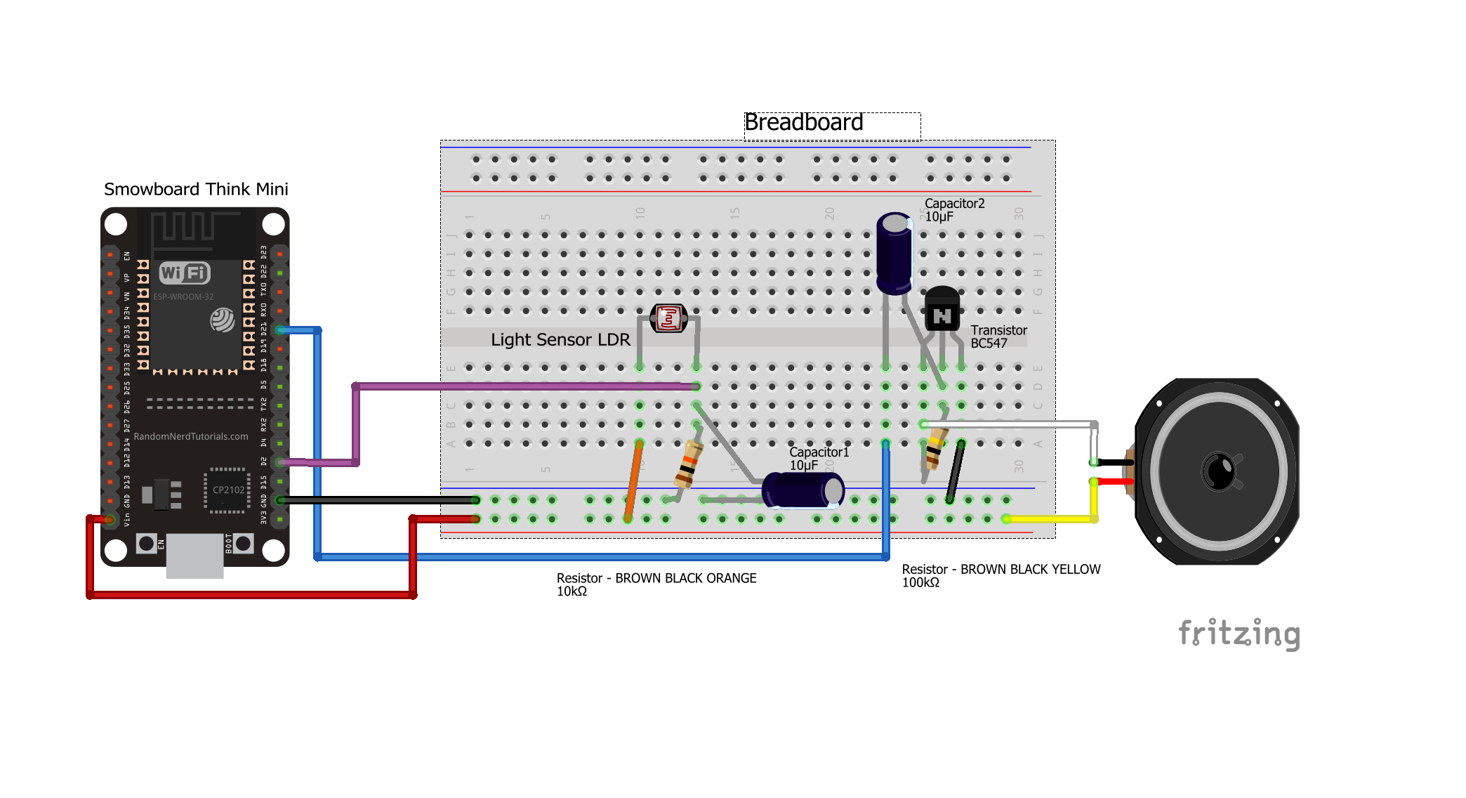
In this circuit, we connect a transistor on the breadboard. We connect the 100k ohm resistor across the base-collector junction of the transistor. We connect the negative terminal of the capacitor to the base of the transistor and the positive terminal of the capacitor to the pin number 21 of Smowboard. We connect one terminal of the speaker to Vin pin of the Smowboard while its other terminal is connected to the collector of transistor. The emiiter of the transisitor is grounded by connecting it to the ground of Smowboard. We connect an LDR on the breadboard. We connect the positive terminal of the capacitor and one terminal of the 10k ohm resistor to one pin of the LDR. We connect this pin of the LDR to the pin number 13 of Smowboard. The other teminal of the capacitor as well as the resistor is connected to the ground of the Smowboard. We connect the other pin of the LDR to the Vin pin of the Smowboard.
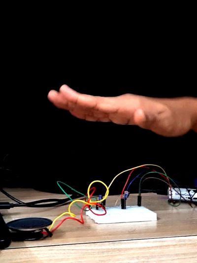
The speaker is connected to the Smowboard using capacitor and transistor. The Smowboard controls the frequency of the sound. When the hand is moved over the LDR sensor, the resistane values varies due to change of intensity. Smowboard reads different values of LDR and accordingly maps it to a specific frequency of sound. Thus, when a hand is moved over the LDR, different frequencies of sound are obtained due to variation in intensity.
Flow

[{"id":"a530204c.74db4","type":"tab","label":"Flow 1","disabled":false,"info":""},{"id":"f0b16af8.37d528","type":"common/on interval","z":"a530204c.74db4","config_props":{"name":"","interval":"0.05"},"outputProps":{},"dependency_set":{},"x":270,"y":180,"wires":[["f62e585e.1df4f8"]]},{"id":"f62e585e.1df4f8","type":"smow_adc/analog read","z":"a530204c.74db4","config_props":{"name":"","config":"1793ef07.5602f1"},"outputProps":{},"outputs":[{"variables":[{"name":"digital value","value":"digital_value"}]}],"dependency_set":{},"x":460,"y":180,"wires":[["9ee91d31.4d70a"]]},{"id":"9ee91d31.4d70a","type":"smow_util/map","z":"a530204c.74db4","config_props":{"name":"","input":"digital_value","x1":"0","x2":"4095","y1":"700","y2":"4000"},"outputProps":{},"outputs":[{"variables":[{"name":"mapped","value":"mapped"}]}],"dependency_set":{},"x":690,"y":180,"wires":[["d9f5fd20.804d6"]]},{"id":"d9f5fd20.804d6","type":"smow_pulse/sound","z":"a530204c.74db4","config_props":{"name":"","config":"66ba6ca0.598884","on_off":"1","frequency":"mapped"},"outputProps":{},"dependency_set":{"switch_on":true},"x":930,"y":180,"wires":[[]]},{"id":"1793ef07.5602f1","type":"smow_adc/adc config","z":"","config_props":{"name":"","input_type":"0","pin":"13","non_gpio_input":"0","atten":"3","adc_bit_width":"3","samples":"2","v_ref":"1100","unit":"1","channel":"4"},"outputProps":{},"dependency_set":{"false_dep":false,"input_type_pin":true,"input_type_non_gpio_pad":false,"adc_unit1":false,"adc_unit2":true,"adc_ch0":false,"adc_ch1":false,"adc_ch2":false,"adc_ch3":false,"adc_ch4":true,"adc_ch5":false,"adc_ch6":false,"adc_ch7":false,"adc_ch8":false,"adc_ch9":false}},{"id":"66ba6ca0.598884","type":"smow_pulse/analog write config","z":"","config_props":{"name":"","pin":"21","duty_resolution":"11","timer_num":"0","led_channel":"0","clk_config":"0","speed_mode":"0"},"outputProps":{},"dependency_set":{}}]
To import this code to the Studio, copy it and paste it into the import nodes dialog box in the import section.
Lets understand the code,
- The flow starts with an
on intervalnode. All next nodes connected to it get triggered repeatedly after the specified interval of time. - Double click on the node to change its properties.
- We set the time interval of the
on-intervalnode to 0.05 seconds. - We connect an
analog readnode to read the analog values from the LDR. This will define the intensity of sound for the speaker. Configure the node by clicking on the pencil icon on the input property of the node. Set the 'Pin' value as 13. Set the 'voltage range' as 150 - 2450mV (attenuation 11dB). - We then click on
Addanddoneto complete the configuration. - The output of this node is 'digital_value' which will be passed on to the next node.
- Now, we connect a
mapnode to map the 'digital_values' variable which is the output of theanalog readnode. For this, we set the 'input' property of the node as 'digital_values'. Set the properties x1 , x2 , y1 and y2 as 0, 4095, 700 and 4000 respectively. - The output of this node is 'mapped' which will be passed on to the next node.
- This will map the analog values obtained from LDR to a scale from 700 to 4000.
- We use a
soundnode to get the audio output from the speaker. Configure thesoundnode by clicking on the pencil icon on the 'Output' property of the node. Set the 'Output pin' to 21 as we have connected the speaker output to pin number 21 of Smowboard. - We then click on
Addanddoneto complete the configuration. - We set the 'switch' property as 'Turn ON' and set the 'tone' to 'mapped' variable which is the output obtained from the
mapnode. - The speaker will produce sound of frequency obtained from the
mapnode. - Now, we upload the code to the Smowboard using the
uploadbutton on the Studio. - We can see, when we move our hand over the LDR, the intensity of light keeps varying due to which the
analog readnode reads different values. Thus, sounds of different frequencies are produced giving the effect of an orchestra.
Output
Learn Coding and Electronics easily using Smowcode.